Showing posts with label Design. Show all posts

Wednesday, July 23, 2008

Introducing the CSX Dixie Line


I have changed my prototype from the CSX former Clinchfield route to the CSX line between Atlanta, GA and Nashville, TN via Chattanooga, TN. While I really have a special place in my heart for the Clinchfield, I really wanted to have some variety with regards to industrial swithching & operations that were just not available with the Clinchfield. While I will be losing perhaps the best mountain railroad scenery east of the Mississippi, I will be gaining the beautiful scenery of the rolling hills and mountains of northwest Georgia and southeast Tennessee. I feel this is an ideal tradeoff, plus don't be surprised if some Clinchfield inspiration shows up here and there on the new CSX Dixie Line.

Note: This blog has been replaced by the new CSX Dixie Line blog. No additional updates will be made to this CSX Clinchfield Division blog. As always, thanks for visiting and looking forward to seeing you on the new blog!

.

Saturday, July 5, 2008

Full Size Mockups to Establish Layout Height and Depth

I recently built a six foot wide full size mockup of the layout using inexpensive steel shelf brackets and extruded foam to mimic the benchwork, plus construction paper to act as the fascia boards and add a bit of simulated color. The purpose of this exercise was so that I could get a pretty good feeling for what the layout will look and feel like in its finished form, while using cheap materials that could be thrown together quickly and then taken down with ease. I have included a complete set of photos below to show how I went about building and testing the mockups.

Aside from determining whether or not the general layout shape (narrow, long, multi-level around-the-wall shelves) would work in the layout room, I had two specific goals: (1) determine the height of each of the three decks and (2) determine the depth of the shelves. I successfully fulfilled both of these objectives.

Layout Height

The three decks--lower, middle, and upper/staging--will be built at the following heights (measured from floor level to the tops of the joists that support each deck): 42", 57" and 69". I determined these to be the ideal heights by standing back from the mockup in a spot where I believe most operators will stand when running trains. These heights insure that the entire depth of the lower two shelves can be seen and that no layout "innards" (benchwork, wiring, etc.) can be seen by an operator of my height (5' - 8" tall) while standing in the aisles. I also selected these heights because they allow for deck separations of 15" between the lower two levels and 12" between the upper two levels. My helix will rise 2.5" per turn, so 15" separation equals six turns of the helix and 12" equals a bit less than four turns of the helix (any minor height differences can be easily solved by adjusting the transition ramps entering and leaving the helix).

Also note that the upper staging level, at 69" above floor level, will be unseen by even the tallest operators thanks to the elevation plus fascia boards that will extend even a few inches higher. This upper level fascia will double as a view block and a safety fence to prevent trains from plummeting six feet to the floor below. This hidden staging level will be operated via the use of mirrors or cameras and a monitor. Staging will be implemented so that no switching will occur in the staging yards during an operating session.

Layout Depth

With the layout height goal achieved, I set out to determine the layout depth, or the distance between the front edge of the layout and the wall of the train room (or the distance between the front edge of the layout and the peninsula supports for the two shelves running down the middle of the room). My track plan as drawn up in its initial version limits the shelves to a 12" depth around the room, with the exception of one stretch along a short wall of the room that could be 18" deep to accommodate a signature scene to be modelled. I arrived at the standard 12" width as follows:

-- the room is 110" wide
-- the minimum aisle width is 30" and there are two aisles; 30 * 2 = 60" for aisles, leaving 50" for shelves
-- there are four shelves (two along the wall and two down the peninsula)
-- dividing the 50" available shelf space evenly amongst the four shelves allowed 12" for each shelf, plus two inches left over to be contributed to the aisle space
-- four 12" shelves plus two 31" aisles equals 110", or precisely the width of the train room

However, as I thought about this I realized that 12" really leaves enough room for one or two main tracks, some scenery, and not much else. Admittedly there is not much online industry along the Clinchfield mainline, but I did want to leave open the possibility of adding a tipple here or a mine there for some operational variety, and 12" just wasn't going to allow for that. And what about a yard? A small one would not be impossible in 12", but there would be little room for anything other than the tracks, which would make it look more like a staging yard rather than an operating, scenicked part of the layout.

Therefore, when I built the mockup shelves out of 6 foot long sections of 3/4" blue extruded foam, I started off by making each shelf 16" deep. I then laid down some brown construction paper to give the shelf a more realistic "dirt" look and taped 4" wide strips of black paper along the front edge to simulate the fascia. On top of the brown paper, I placed track, some rolling stock, and a few building mockups I built a while back out of poster board--enough stuff to allow a limited yet usable view of what the items would look like in a real layout setting. By viewing this configuration from multiple angles, I determined that a depth of 16" would be adequate to allow for some sort of switching industry or even a small functioning (and realistic looking!) yard.

Next, I cut the back 4" off each shelf and placed them back on the brackets so that I now had a 12" depth across all three decks. While it became clear that 12" would not support a medium sized industry or yard, I was surprised at how much space was available even with two main tracks running through the scene. In fact, I am really looking forward to laying out some passing siding or bridge scenes that I think will actually take advantage of the long & narrow shelf areas of the layout.

Putting this information all together, I will be altering the track plan as follows: the width of three of the shelves will be reduced from 12" to 11", while the width of the fourth shelf (the long one against the back wall of the room) will be widened to 17". While the one inch reduction of the three shelves will have minimal impact, the width added to the fourth shelf will be significant: I will have a 17" wide shelf on all decks that will be 18'-2" long on the back wall. Plus, this will join on one end to the already wider shelf along one of the short 9'-2" walls, so I will basically have an L-shaped section over 27 feet long that will have at least a 17" width. This should be more than enough real estate to do what I want with regards to industries, towns and yards.

Photos


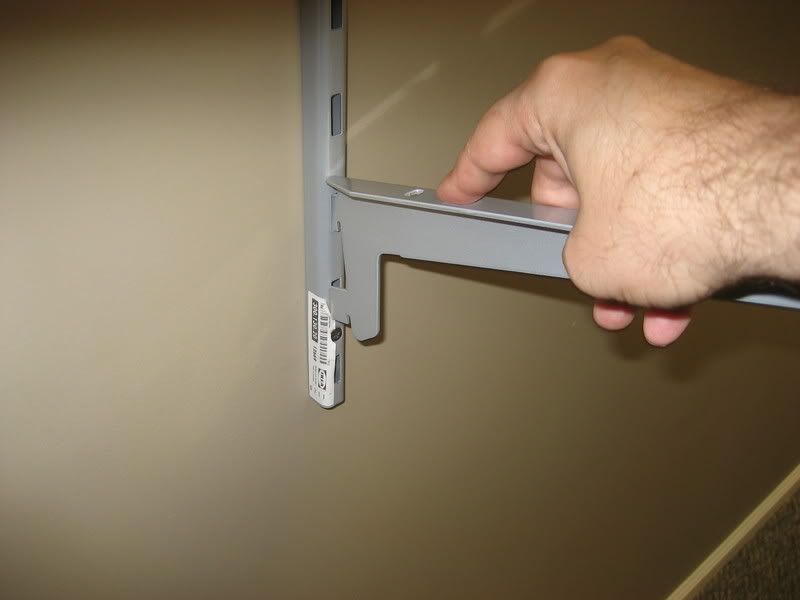
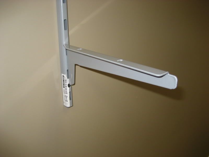
Figure 1 The first metal shelf wall bracket has been installed. I purchased this particular shelving system from Ikea; pricing was about $3 for a pair of wall brackets and $2 for a pair of shelf brackets.


Figure 2 Installing a shelf bracket into a wall bracket. I could easily adjust the height of the shelves in 2" increments simply by moving the bracket up or down into the adjacent slots in the wall bracket.


Figure 3 The first shelf bracket installed in the wall bracket.


Figure 4 The first 3/4" blue foam shelf has been installed on a pair of brackets. I would later add a third wall bracket because the 6' wide pieces of foam sagged a bit in the middle.


Figure 5 Closeup of both decks from the viewpoint of a 5'-8" tall operator. Some track, rolling stock and a few paper buildings have been added to give a sense of the final dimensions and arrangement. The brown paper simulates a "dirt" color; there seems to be a river in the foreground of the lower deck!


Figure 6 Closeup of the middle deck from the viewpoint of a 5'-8" tall operator. Notice that you can see the underside of the upper deck; the fascia will prevent this from happening on the actual layout.


Figure 7 Closeup of the lower deck from the viewpoint of a 5'-8" tall operator.


Figure 8 Far away view of the entire 6' wide layout section mockup with black paper added to simulate fascia. An operator will not be able to stand this far back from the shelves once the layout is complete.


Figure 9 A straight-on view of both decks with the fake fascia in place.


Figure 10 An angled view of both decks with the fake fascia in place.

.

Monday, June 30, 2008

The Train Room

The N-scale CSX Clinchfield Division layout will occupy a basement room that is 18’-2” long by 9’-2” wide, or roughly 162 square feet in area. This room, which has no windows and a single 36” wide opening (with no door) along one of the long walls, was finished along with most of the basement in the spring of 2002. The floor is covered with padded, commercial grade carpeting and the ceiling features a 2’ x 2’ suspended ceiling grid hung at 9’ above floor level. There are three commercial grade 2’ x 4’ fluorescent lighting fixtures recessed into the ceiling and abundant electrical outlets. This room is wired on an independent 15 amp branch circuit. The entire basement is climate controlled with regards to heating & air conditioning and humidity.

There is really only one hard political constraint with regards to the layout: it must fit entirely in this single room. This includes all mainline, branchline and staging areas. While future expansion may reach into adjoining rooms, I have decided that setting the political boundary to the confines of this single room is the best way to get started and will discourage me from biting off more than I can chew (as if I haven't done this already!). This also means that there will be no carpentry involved with the room itself other than attaching benchwork to the walls as needed. Most importantly, none of my beautiful drywall will need to be punched through!

Photos

Here is a diagram of the room that will house the CSX Clinchfield Division layout (click any picture for larger version):


Here is a view looking away from the entrance. The helix will be in the distance at the end of the peninsula that runs down the middle of the long axis of the room:


Here is a view looking back the other way towards the entrance. The peninsula will attach to the middle of the short wall, or just behind where my current test layout is:


Here is my current test layout and a small 2' x 4' layout:


The test layout is built on a hollow core interior door mounted on folding banquet table legs. I believe it uses the same track plan that Dave Vollmer's N Scale Pennsy Middle Division layout is based on. I hope to have just a bit of the same success that Dave has had with his impressive layout!

Monday, June 23, 2008

Track Plan

These are the current track plan diagrams for the N-scale CSX Clinchfield Division layout. For previous versions of the track plan, click one of the following links:

Track Plan at a Glance

Name: CSX Clinchfield Division
Scale: N (1:160) Size: 18'-2" x 9'-2"
Prototype: CSX former Clinchfield route
Period: Modern
Style: Multi-deck, around the walls with peninsula
Mainline run: 132 feet (not including staging or helix)
Minimum radius: 15"
Minimum turnout: no. 10 on mainline, no. 5 branch & staging
Maximum grade: 2.7 percent in helix


Sunday, June 22, 2008

Track Plan v1.0

The track plan for the N-scale CSX Clinchfield Division layout is shown in the diagrams below. It should be noted that this is merely the first version of the track plan and as with all model railroads, many revisions and variations can be expected over time. Also, I have only roughed in the general path of the mainline--there are no sidings, spurs or branches on the plan at this time. In general I plan to have two usable passing sidings on each level to accommodate operational requirements such as meets and helper service.

You will also notice that there are no specific towns or stations on the track plan at this time. Instead, I have roughed in several locations for "scenes" which will eventually be replaced by towns, stations and industries once I have settled on the specific section of the prototype I will model. As it is, I have placed five potential scenes on each level along the straightaways. This provides for 10 individual scenes, which have been labelled using the letters "A" through "J." If you follow a southbound train out of the north staging yard, you will traverse the layout in alphabetical order starting with scene "A" and ending with scene "J" before ending up in the south staging yard. As the plan evolves, I will begin replacing these lettered scenes with the names of the actual locations to be modeled.

Track Plan at a Glance

Name: CSX Clinchfield Division
Scale: N (1:160)
Size: 18'-2" x 9'-2"
Prototype: CSX former Clinchfield route
Period: Modern
Style: Multi-deck, around the walls with peninsula
Mainline run: 132 feet (not including staging or helix)
Minimum radius: 15"
Minimum turnout: no. 10 on mainline, no. 5 branch & staging
Maximum grade: 2.7 percent in helix

Pros

  • Layout fits into one room This satisfies the primary political restriction imposed on the layout. Negotiations for right-of-way into other rooms can be deferred until necessary.
  • Long length of mainline run Despite the single room restriction, the multiple deck design allows for 132 feet of mainline track, or roughly four scale miles (two miles per deck). This comes out to about 66 feet of track per deck and when you factor in a maximum train length of around 10 feet, it means each deck can have about six blocks. This will allow room for two passing sidings plus four other blocks, with a goal of having two blocks between the passing sidings.
  • Plenty of staging There are two staging yards on the upper deck of the layout (north and south) that represent the unseen points beyond the "end" of the visible track. Both staging yards have six double ended tracks that have enough length to hold the longest trains that will run on the layout. In fact, the longest tracks have the ability to hold more than one train to allow for serialized staging if desired. There is also ample space to lengthen one of the staging yards as needed.
  • Hidden staging above the layout I originally had this feature in the "cons" section below, but upon further review I have decided this is most definitely a "pro." By placing the staging on top of the layout, I feel I am taking advantage of the fact that this space is readily available on top of the valance for the middle deck and also that a simple extension of the helix allows this space to be reached fairly easily. I plan on having the staging yard "accessible" via the use video cameras and monitors, although time will tell if this feature actually comes to fruition or is simply pie in the sky. In lieu of cameras and monitors, the old reliable combination of mirrors and step ladders should do just fine in providing access to the staging yards.
  • Directional continuity On this track plan north is always to the left and south is always to the right no matter which part of the layout is being viewed. This means engineers following their trains will not be confronted with confusing reversals of direction along their route.
  • Continuous running A northbound train exiting the layout on the north end will eventually re-enter the layout on the south end, and vice-versa for northbound trains. I believe this is a very important feature when planning a layout that could be operated by a single operator, since you can put one (or more depending on how lucky you feel!) trains into motion in one direction and let them orbit the layout while the operator runs his train in the opposite direction and tries to keep out of the path of the oncoming traffic. This will also be a useful feature when showing the layout to others.
  • Build in phases Another important feature of the multi-deck arrangement is that the layout can be built in phases, allowing me to build as little or as much layout as time and resources allow. For example, the first phase to be built will be the lower level. When this is done, only a small portion of the helix will need to be built to function as a return loop at the end of the peninsula. I can then move on to the middle deck and eventually the top staging deck, expanding the helix as necessary as I go.

Cons

  • The insatiable appetite of the helix Each turn of the helix gains 2.5 inches of elevation and takes about eight feet of track. There are 6 turns of the helix between the lower and middle decks and 4 turns between the middle and upper decks. This means that a train traversing the entire helix from the lower deck to the upper (staging) deck will require 10 turns, which is about 80 feet of track, which is about 2 1/2 scale miles! However, I feel this part of the design is a necessary evil and is a acceptable trade off for many of the advantages that this track plan offers. Additionally, there are several well known layouts that successfully employ a similar helix strategy. By placing the helix at the end of the peninsula, I have also provided ready access to the helix from outside or inside. The helix will be hidden from view by use of either a curtain or a removable hardboard fascia.
  • Narrow aisles The track plan as designed uses a standard aisle width of 30", which is about 6 inches narrower than what is preferred. However, since the layout is planned for only one or two operators, this should not pose much of a problem. It is also the widest aisles I could accommodate while still allowing for the peninsula in the middle of the room. Controls will be minimized along the layout fascia to reduce the risk of operators getting snagged on switches and indicators.
  • Long, straight scenes While this may be preferred for Midwest Granger layouts, it is going to be tricky to represent a twisting route through the Appalachians on a shelf that in some places is one foot wide by 18 feet long! However, I believe I can mitigate this by keeping straight track to a minimum and using abundant view blocks to trick the eye into not seeing a straight line. I also plan to keep as much curved track out in the open while any hidden track (such as in tunnels) is on tangent sections.