
This blog has been discontinued.
Please visit my new blog for the CSX Dixie Line.
If you do not click the above link,
you will automatically be redirected in 5 seconds.


Name: CSX Clinchfield Division
Scale: N (1:160)
Size: 18'-2" x 9'-2"
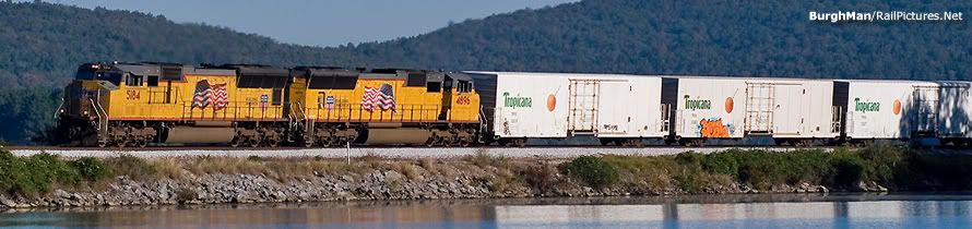
Prototype: CSX former Clinchfield route
Period: Modern
Style: Multi-deck, around the walls with peninsula
Mainline run: 132 feet (not including staging or helix)
Minimum radius: 15"
Minimum turnout: no. 10 on mainline, no. 5 branch & staging
Maximum grade: 2.7 percent in helix


 Construction began on the Carolina Clinchfield and Ohio Railway (CC&O) at the end of the 19th century. The railroad was built to haul coal out of the fields of western Virginia to the markets in the south, primarily the textile mills in the Carolinas. There was already plenty of competition in the area at the time, and numerous failed efforts almost doomed the fledgling railroad before it ever really got going. Ironically, these false starts turned out to be quite advantageous—by the time work resumed under new ownership at the start of the 20th century, the railroad was able to take advantage of many technological advancements in construction that were not available to the competition when they were built decades earlier. Additionally, the railroad was constructed to very high standards for the era which resulted in a straighter, more level and most importantly faster route to deliver goods to market. While this made the Clinchfield the "costliest railroad to cross the Blue Ridge," current operator CSX has not had to improve curves, grades or clearances due to the introduction of heavier and larger modern day equipment. Finally, a northern extension connected the Clinchfield to the Chesapeake & Ohio at Elkhorn City, Ky. This critical link established the line as a major bridge route between the southeast and the midwest and cemented the Clinchfield's prominence in eastern railroading lore. In 1972, the Clinchfield came under the umbrella of the Family Lines System, which then became Seaboard System and eventually today's CSX.
When the new owners stepped in to finish construction of the Clinchfield in the early 1900's, their dream was to have a railroad to connect the coalfields of Kentucky and Virginia with the Ohio River ports to the north and the Atlantic ports to the south. Although the Clinchfield did indirectly reach the Ohio River via the connection to the C&O, the connection to the Atlantic ports never materialized as the line only reached as far south as Spartanburg in the upstate part of South Carolina. Meanwhile, in the mid 1920's, the C&O was looking for access to additional ports along the Atlantic coast to meet the exploding demand for export coal. The C&O already had a port facility in the Tidewater area, but the rail lines to reach this port and the facility itself were quickly reaching capacity. Rather than expand capacity at the existing Tidewater port, the C&O entered into a partnership with the Clinchfield where the rail line would be extended from the current terminus in Spartanburg all the way to the Atlantic coast port city of Charleston, SC. The C&O would build this “Clinchfield Extension” and in return would receive trackage rights over the "old" Clinchfield via the connection at Elkhorn City. Of course the Clinchfield received reciprocal trackage rights over the new line and also used the new Charleston port facility. Under this arrangement, the export coal on the C&O from West Virginia continued to use the Tidewater port while export coal from Kentucky flowed southward over the new Clinchfield Extension to the port at Charleston. This project turned out to be a financial boom for both railroads for nearly three decades until the export coal business dropped off significantly in the mid 1950's. In later years, the Clinchfield Extension saw less and less coal traffic and more and more freight traffic as the volume of imported containerized merchandise skyrocketed. Eventually the Clinchfield and C&O came together as CSX via the Family Lines/Seaboard System lineage that we all know. The South Carolina Ports Authority opened the new state-of-the-art Wando Terminal in the late 1980's adjacent to the coal docks, and today CSX enjoys exclusive rail access to this port for intermodal traffic (although the Norfolk Southern does have limited trackage rights). Containers coming in to the Port of Charleston reach the heartland of the USA swiftly thanks to the outstanding engineering effort put forth when constructing the Clinchfield almost 100 years earlier. This port is also used for export grain and import automotive business, making the former Clinchfield route and the Clinchfield Extension one of the most vital links in the CSX transportation network. The former C&O Big Sandy subdivision, the former Clinchfield Railroad and the C&O Clinchfield Extension now make up the CSX Clinchfield Division, with division headquarters in Erwin, TN.

