I recently built a six foot wide full size mockup of the layout using inexpensive steel shelf brackets and extruded foam to mimic the benchwork, plus construction paper to act as the fascia boards and add a bit of simulated color. The purpose of this exercise was so that I could get a pretty good feeling for what the layout will look and feel like in its finished form, while using cheap materials that could be thrown together quickly and then taken down with ease. I have included a complete set of photos below to show how I went about building and testing the mockups.
Aside from determining whether or not the general layout shape (narrow, long, multi-level around-the-wall shelves) would work in the layout room, I had two specific goals: (1) determine the height of each of the three decks and (2) determine the depth of the shelves. I successfully fulfilled both of these objectives.
Layout HeightThe three decks--lower, middle, and upper/staging--will be built at the following heights (measured from floor level to the tops of the joists that support each deck): 42", 57" and 69". I determined these to be the ideal heights by standing back from the mockup in a spot where I believe most operators will stand when running trains. These heights insure that the entire depth of the lower two shelves can be seen and that no layout "innards" (benchwork, wiring, etc.) can be seen by an operator of my height (5' - 8" tall) while standing in the aisles. I also selected these heights because they allow for deck separations of 15" between the lower two levels and 12" between the upper two levels. My helix will rise 2.5" per turn, so 15" separation equals six turns of the helix and 12" equals a bit less than four turns of the helix (any minor height differences can be easily solved by adjusting the transition ramps entering and leaving the helix).
Also note that the upper staging level, at 69" above floor level, will be unseen by even the tallest operators thanks to the elevation plus fascia boards that will extend even a few inches higher. This upper level fascia will double as a view block and a safety fence to prevent trains from plummeting six feet to the floor below. This hidden staging level will be operated via the use of mirrors or cameras and a monitor. Staging will be implemented so that no switching will occur in the staging yards during an operating session.
Layout DepthWith the layout height goal achieved, I set out to determine the layout depth, or the distance between the front edge of the layout and the wall of the train room (or the distance between the front edge of the layout and the peninsula supports for the two shelves running down the middle of the room). My track plan as drawn up in its initial version limits the shelves to a 12" depth around the room, with the exception of one stretch along a short wall of the room that could be 18" deep to accommodate a signature scene to be modelled. I arrived at the standard 12" width as follows:
-- the room is 110" wide
-- the minimum aisle width is 30" and there are two aisles; 30 * 2 = 60" for aisles, leaving 50" for shelves
-- there are four shelves (two along the wall and two down the peninsula)
-- dividing the 50" available shelf space evenly amongst the four shelves allowed 12" for each shelf, plus two inches left over to be contributed to the aisle space
-- four 12" shelves plus two 31" aisles equals 110", or precisely the width of the train room
However, as I thought about this I realized that 12" really leaves enough room for one or two main tracks, some scenery, and not much else. Admittedly there is not much online industry along the Clinchfield mainline, but I did want to leave open the possibility of adding a tipple here or a mine there for some operational variety, and 12" just wasn't going to allow for that. And what about a yard? A small one would not be impossible in 12", but there would be little room for anything other than the tracks, which would make it look more like a staging yard rather than an operating, scenicked part of the layout.
Therefore, when I built the mockup shelves out of 6 foot long sections of 3/4" blue extruded foam, I started off by making each shelf 16" deep. I then laid down some brown construction paper to give the shelf a more realistic "dirt" look and taped 4" wide strips of black paper along the front edge to simulate the fascia. On top of the brown paper, I placed track, some rolling stock, and a few building mockups I built a while back out of poster board--enough stuff to allow a limited yet usable view of what the items would look like in a real layout setting. By viewing this configuration from multiple angles, I determined that a depth of 16" would be adequate to allow for some sort of switching industry or even a small functioning (and realistic looking!) yard.
Next, I cut the back 4" off each shelf and placed them back on the brackets so that I now had a 12" depth across all three decks. While it became clear that 12" would not support a medium sized industry or yard, I was surprised at how much space was available even with two main tracks running through the scene. In fact, I am really looking forward to laying out some passing siding or bridge scenes that I think will actually take advantage of the long & narrow shelf areas of the layout.
Putting this information all together, I will be altering
the track plan as follows: the width of three of the shelves will be reduced from 12" to 11", while the width of the fourth shelf (the long one against the back wall of the room) will be widened to 17". While the one inch reduction of the three shelves will have minimal impact, the width added to the fourth shelf will be significant: I will have a 17" wide shelf on all decks that will be 18'-2" long on the back wall. Plus, this will join on one end to the already wider shelf along one of the short 9'-2" walls, so I will basically have an L-shaped section over 27 feet long that will have at least a 17" width. This should be more than enough real estate to do what I want with regards to industries, towns and yards.
Photos Figure 1
 The first metal shelf wall bracket has been installed. I purchased this particular shelving system from Ikea; pricing was about $3 for a pair of wall brackets and $2 for a pair of shelf brackets.
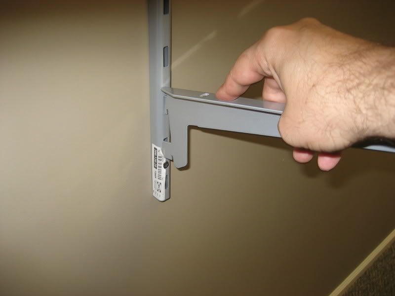 Figure 2
 Installing a shelf bracket into a wall bracket. I could easily adjust the height of the shelves in 2" increments simply by moving the bracket up or down into the adjacent slots in the wall bracket.
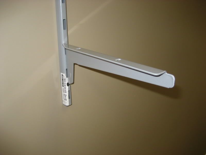 Figure 3
 The first shelf bracket installed in the wall bracket.
 Figure 4
 The first 3/4" blue foam shelf has been installed on a pair of brackets. I would later add a third wall bracket because the 6' wide pieces of foam sagged a bit in the middle.
 Figure 5
 Closeup of both decks from the viewpoint of a 5'-8" tall operator. Some track, rolling stock and a few paper buildings have been added to give a sense of the final dimensions and arrangement. The brown paper simulates a "dirt" color; there seems to be a river in the foreground of the lower deck!
 Figure 6
 Closeup of the middle deck from the viewpoint of a 5'-8" tall operator. Notice that you can see the underside of the upper deck; the fascia will prevent this from happening on the actual layout.
 Figure 7
 Closeup of the lower deck from the viewpoint of a 5'-8" tall operator.
 Figure 8
 Far away view of the entire 6' wide layout section mockup with black paper added to simulate fascia. An operator will not be able to stand this far back from the shelves once the layout is complete.
 Figure 9
 A straight-on view of both decks with the fake fascia in place.
 Figure 10
 An angled view of both decks with the fake fascia in place.
.